
Power System Dynamics and Stability With Synchrophasor Measurement and Power System Toolbox
Aus der Reihe
Wiley - IEEE
-
- Englisch ausgewählt
167,99 €
inkl. gesetzl. MwSt.,
Beschreibung
Produktdetails
Einband
Gebundene Ausgabe
Erscheinungsdatum
25.09.2017
Verlag
John Wiley & Sons IncSeitenzahl
374
Maße (L/B/H)
25/17,5/2,5 cm
Gewicht
771 g
Auflage
2. Auflage
Sprache
Englisch
ISBN
978-1-119-35577-9
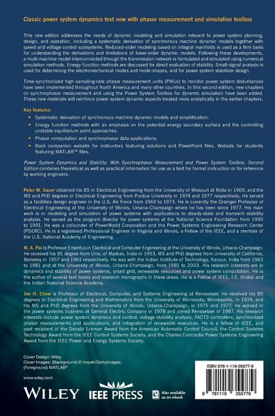
Classic power system dynamics text now with phasor measurement and simulation toolbox
This new edition addresses the needs of dynamic modeling and simulation relevant to power system planning, design, and operation, including a systematic derivation of synchronous machine dynamic models together with speed and voltage control subsystems. Reduced-order modeling based on integral manifolds is used as a firm basis for understanding the derivations and limitations of lower-order dynamic models. Following these developments, multi-machine model interconnected through the transmission network is formulated and simulated using numerical simulation methods. Energy function methods are discussed for direct evaluation of stability. Small-signal analysis is used for determining the electromechanical modes and mode-shapes, and for power system stabilizer design.
Time-synchronized high-sampling-rate phasor measurement units (PMUs) to monitor power system disturbances have been implemented throughout North America and many other countries. In this second edition, new chapters on synchrophasor measurement and using the Power System Toolbox for dynamic simulation have been added. These new materials will reinforce power system dynamic aspects treated more analytically in the earlier chapters.
Key features:
* Systematic derivation of synchronous machine dynamic models and simplification.
* Energy function methods with an emphasis on the potential energy boundary surface and the controlling unstable equilibrium point approaches.
* Phasor computation and synchrophasor data applications.
* Book companion website for instructors featuring solutions and PowerPoint files. Website for students featuring MATLAB files.
Power System Dynamics and Stability, 2nd Edition, with Synchrophasor Measurement and Power System Toolbox combines theoretical as well as practical information for use as a text for formal instruction or for reference by working engineers.
Kundinnen und Kunden meinen
Verfassen Sie die erste Bewertung zu diesem Artikel
Helfen Sie anderen Kund*innen durch Ihre Meinung
Kurze Frage zu unserer Seite
Vielen Dank für Ihr Feedback
Wir nutzen Ihr Feedback, um unsere Produktseiten zu verbessern. Bitte haben Sie Verständnis, dass wir Ihnen keine Rückmeldung geben können. Falls Sie Kontakt mit uns aufnehmen möchten, können Sie sich aber gerne an unseren Kund*innenservice wenden.
zum Kundenservice