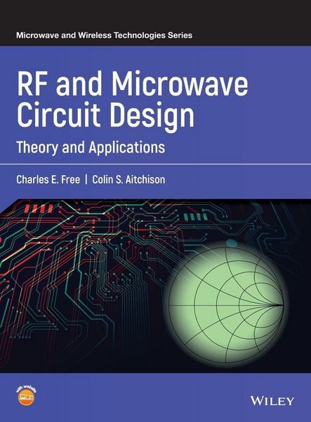
RF and Microwave Circuit Design
-
- Englisch ausgewählt
116,99 €
inkl. gesetzl. MwSt.,
Beschreibung
Produktdetails
Einband
Gebundene Ausgabe
Erscheinungsdatum
21.09.2021
Verlag
John Wiley & Sons IncSeitenzahl
528
Maße (L/B/H)
28,3/22,3/3,7 cm
Gewicht
1446 g
Auflage
1. Auflage
Sprache
Englisch
ISBN
978-1-119-11463-5
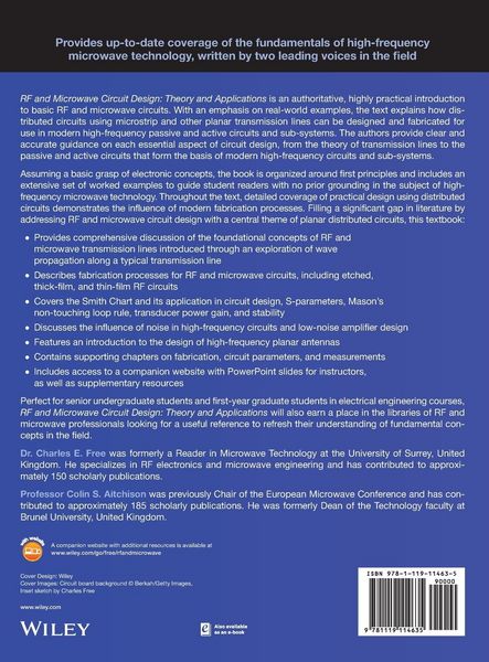
Provides up-to-date coverage of the fundamentals of high-frequency microwave technology, written by two leading voices in the field
RF and Microwave Circuit Design: Theory and Applications is an authoritative, highly practical introduction to basic RF and microwave circuits. With an emphasis on real-world examples, the text explains how distributed circuits using microstrip and other planar transmission lines can be designed and fabricated for use in modern high-frequency passive and active circuits and sub-systems. The authors provide clear and accurate guidance on each essential aspect of circuit design, from the theory of transmission lines to the passive and active circuits that form the basis of modern high-frequency circuits and sub-systems.
Assuming a basic grasp of electronic concepts, the book is organized around first principles and includes an extensive set of worked examples to guide student readers with no prior grounding in the subject of high-frequency microwave technology. Throughout the text, detailed coverage of practical design using distributed circuits demonstrates the influence of modern fabrication processes. Filling a significant gap in literature by addressing RF and microwave circuit design with a central theme of planar distributed circuits, this textbook:
* Provides comprehensive discussion of the foundational concepts of RF and microwave transmission lines introduced through an exploration of wave propagation along a typical transmission line
* Describes fabrication processes for RF and microwave circuits, including etched, thick-film, and thin-film RF circuits
* Covers the Smith Chart and its application in circuit design, S-parameters, Mason???s non-touching loop rule, transducer power gain, and stability
* Discusses the influence of noise in high-frequency circuits and low-noise amplifier design
* Features an introduction to the design of high-frequency planar antennas
* Contains supporting chapters on fabrication, circuit parameters, and measurements
* Includes access to a companion website with PowerPoint slides for instructors, as well as supplementary resources
Perfect for senior undergraduate students and first-year graduate students in electrical engineering courses, RF and Microwave Circuit Design: Theory and Applications will also earn a place in the libraries of RF and microwave professionals looking for a useful reference to refresh their understanding of fundamental concepts in the field.
Noch keine Bewertungen vorhanden
Verfassen Sie die erste Bewertung zu diesem Artikel
Helfen Sie anderen Kundinnen und Kunden durch Ihre Meinung.
Kurze Frage zu unserer Seite
Vielen Dank für Ihr Feedback
Wir nutzen Ihr Feedback, um unsere Produktseiten zu verbessern. Bitte haben Sie Verständnis, dass wir Ihnen keine Rückmeldung geben können. Falls Sie Kontakt mit uns aufnehmen möchten, können Sie sich aber gerne an unseren Kund*innenservice wenden.
zum Kundenservice